10 / 16
DC Motor: PWM Speed & Driver Basics
Adjust a DC motor PWM control and watch the model respond. Understand why a motor needs a driver rather than direct power from an Uno pin.
Run this experiment →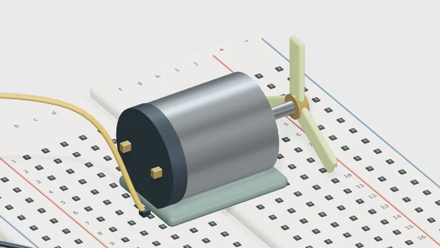
Why it’s here
Set a PWM duty cycle for a conceptual motor driver.
How it works
The PWM value represents a command to a driver stage. Real speed depends on load and supply, so this animation is not an RPM prediction. Never power a motor directly from an I/O pin.
Try it
- Open this experiment
- Run at PWM 64, then 192. Compare the rotation and duty cycle; treat the displayed speed as a teaching illustration.
Connections
- D9 ~ — Driver / transistor input
- External supply — Motor power stage
- GND — Common signal reference
Example sketch
// Pin 9 drives a transistor stage, not a motor directly.

void setup() {
  pinMode(9, OUTPUT);
}

void loop() {
  analogWrite(9, 150);
}
Check your understanding
Can the illustrated RPM predict a real motor’s speed?
Show the answer
No. Real speed depends on the motor, supply, load and driver. The model shows the direction of a control change, not a calibrated motor measurement.