05 / 16
RGB LED: Mix Red, Green & Blue
Adjust three PWM channels to mix RGB light. Make red, yellow and white, and see how each channel changes the LED color.
Run this experiment →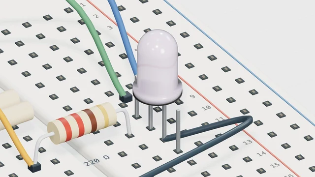
Why it’s here
Control three PWM channels independently.
How it works
Three channels are set independently. Red plus green produces yellow light; equal nonzero values produce neutral light. The model approximates visible color, not LED spectral response or calibrated brightness.
Try it
- Open this experiment
- Set red to 255 and the other channels to 0. Add green at 255, then blue at 255, observing each color change.
Connections
- D9 ~ — Red through resistor
- D10 ~ — Green through resistor
- D11 ~ — Blue through resistor
- GND — Common cathode
Example sketch
void setup() {
  pinMode(9, OUTPUT);
  pinMode(10, OUTPUT);
  pinMode(11, OUTPUT);
}

void loop() {
  analogWrite(9, 180);
  analogWrite(10, 90);
  analogWrite(11, 220);
}
Check your understanding
Which channels make yellow in this model?
Show the answer
Red and green, with blue at zero. This is additive mixing of light, so the result differs from mixing paint.